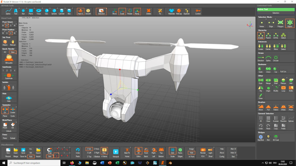
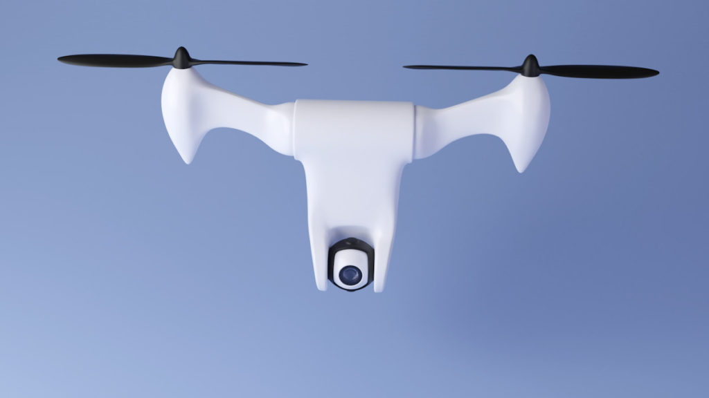
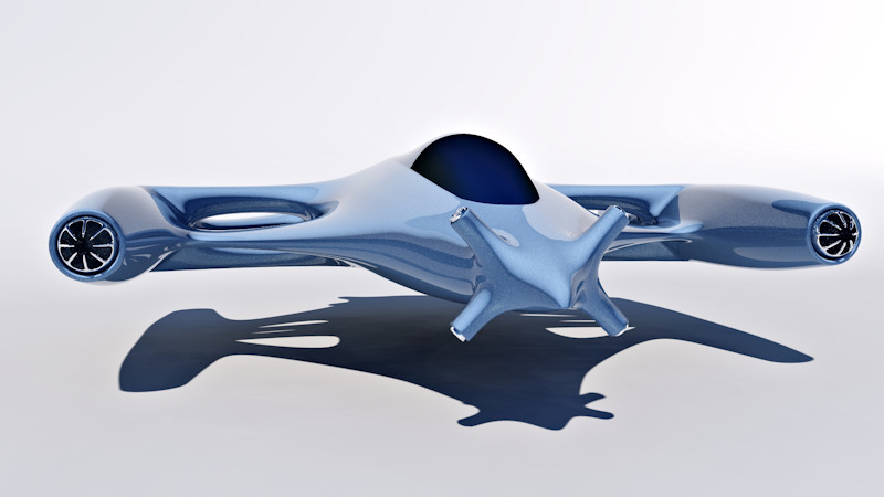
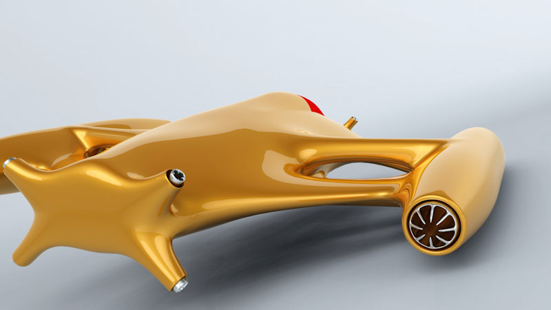
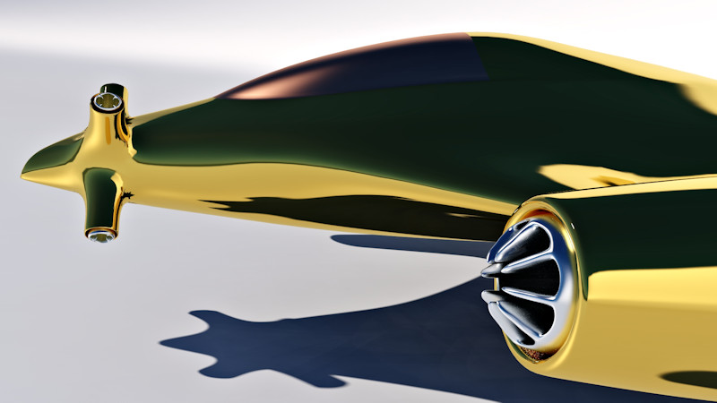
As a second project in polygonal modeling, I created a bicopter drone. To make it fully functional an manouverable, the propeller arms can be rotated. Making the main body of the drone as smooth as possible was quiet difficult (As you can probably see in the lower part of the bicopter).
Modeling was done in Rocket3F once again, but I switched to another renderer. Instead of Simlab, I used Blender. I guess the rendering speed of cycles is a bit higher than Simlab, as it makes useof the GPU as well as the CPU. If I used a better graphics card than my GTX 1030, the difference would be much higher off course. While being slower than Blender, Simlab’s user interface is way more intuitive. But if you are on a tight budget, Blender is absolutely the way to go.
I’ve started polygonmodeling recently, to broaden my CAD horizon (and also because it’s fun!). The model further down below was created in a free modeling program called Rocket 3F. Rocket 3F is free to use like Blender. In comparison to Blender, it is far more intuitive, but limited to modeling (While Blender is basically an all in one 3D-suite). Rendering and post-processing was done in Simlab and Paintshop Pro, as usual.
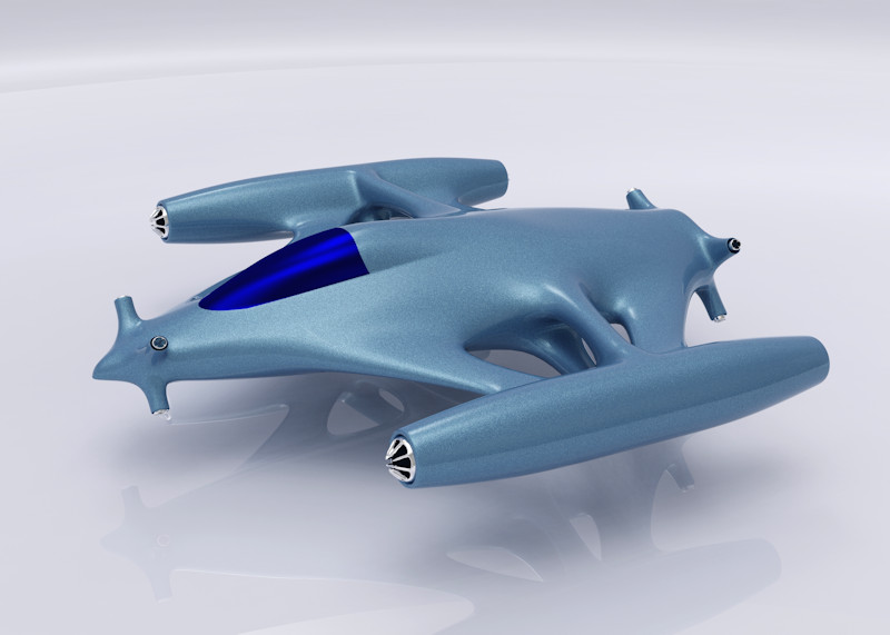
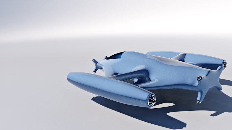
As a fan of SciFi-series like Star Trek and Battlestar Galactica, I thought it’s time to design my own spaceship. It features 4 big main thrusters for acceleration and decelleration and a few smaller thrusters for roll, pitch etc.
Just until recently, 3D-printers were incredibly expensive and unobtainable for Joe Average. Fortunately, this technology has dropped in price significantly over the last few years and it has become hugely popular. For my own personal needs I use a Wanhao i3 Mini, which I use in combination with Viacad Pro. In the next few minutes, I’ll show you some tips and tricks about this topic. So, grab a coffee and fasten your seatbelt. We’re ready to take off!
Designing FDM-friendly parts
The big advantage of 3D-printers is their ability to print highly complex shapes. This allows part-geometries, that are nearly impossible to make, using traditional methods like milling and turning. But even though a 3D-printer can print nearly every shape, there a still quite a few things to consider. A very good starting point for designing FDM-friendly models can be found here:
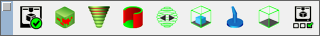
Nowadays, an average slicer like Cura or Simplify3D has all the necessary tools to check your parts for manufacturability. However, Viacad has some built in features as well, which lets you analyze your parts during the whole design process. You can access these tools in Viacad by going to: Windows / 3D Print Tools. The tools in this pallet are fairly simple to use and allow you to check your models very quickly.
3D Print Check This feature is an overall check for your 3d-print.
Surface Normals Checks if all surfaces face in the right direction. You might need this feature, if you work with surfaces and/or imported meshes.
Thickness Using this feature, you can see if all parts of your geometry have the required minimum thickness.
Slices Let’s you slice your object. The slices can also be exported, if needed.
Position Arranges your parts in the build area of your printer. If you want to arrange more than one part, be sure to select them all by dragging a window over them. Shift-Selecting multiple parts seems not to work with this feature!
Structure You probably won’t need this feature, as slicers already have options for support structures.
Volume Shows/hides the build volume of your 3D-printer.Definitions Let’s you define and pick the build volume of your printer (Needed for Volume and 3D Print Check)
Exporting an STL-file
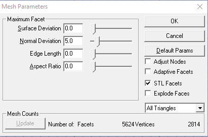
Slicers for 3D-Printers usually need an STL-file, in order to convert your model into a G-code. To export an STL, go to: File / Export, choose STL from the list and click OK. After choosing a file-path, the Mesh Parameter Menu opens up. This menu allows you to change your mesh in various ways. In order to get a nice and clean mesh, you might have to play around with the parameters a little bit. I suggest you try out the parameters one by one, to get a feeling of what they do. Note: You can also type in numbers, to set higher values than achievable by using the sliders!
Here’s a short summary on how these parameters work (Based on my own experience):
Surface Deviation My favorite parameter! It creates a dense mesh in curved shapes of your part while using very few vertices in straight surfaces.
Normal Deviation Similar to Surface Deviation, but with one big drawback: This parameter changes the density of the mesh based on the curvature. That way, a 100mm radius and a 5mm radius have the same number of vertices. This makes Normal Deviation basically unusable if you have parts with big differences in diameters and radii.
Edge Length As the name suggests, this parameter is based on a minimal edge length of the vertices. This creates a very uniform mesh with an extremely high polycount (No matter if your surfaces are flat or curved). I personally use this parameter almost only in combination with Surface Deviation. I first set the Surface Deviation to a fine enough mesh density and then use an Edge Length of a few Millimeters to add a few vertices to flat surfaces. This usually results in cleaner mesh.
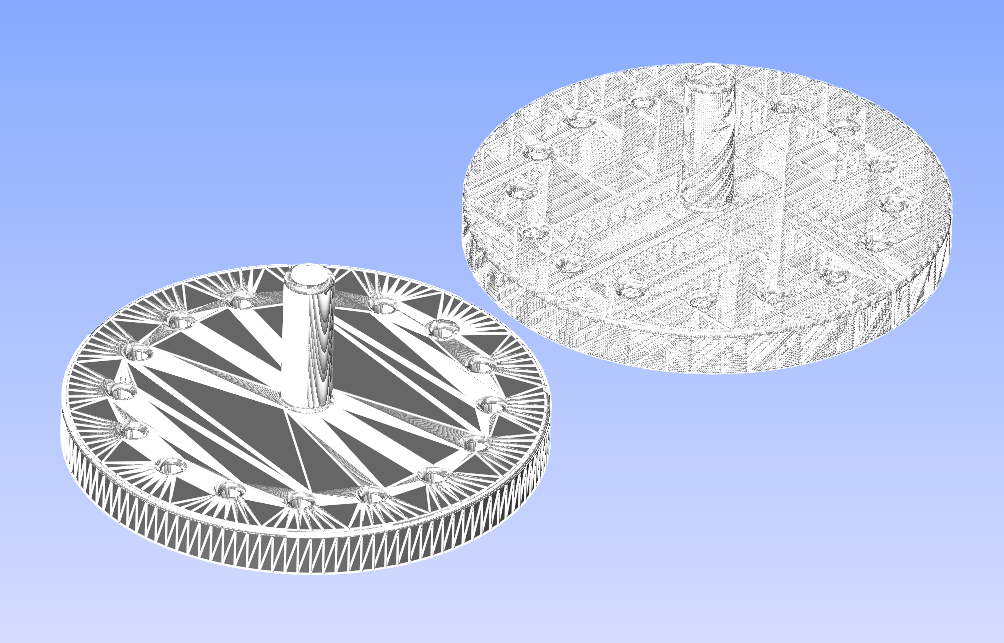
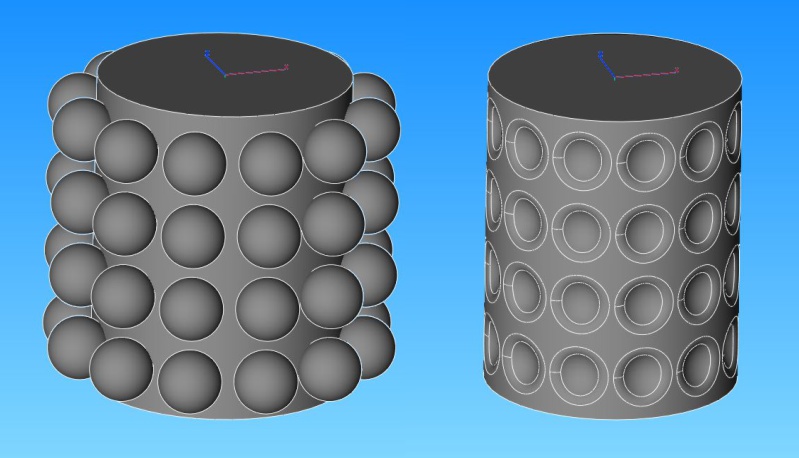
The left mesh in this picture was made using only Normal Deviation, while the right one was made with a combination of Surface Deviation and Edge Length. Both meshes have around 150’000 vertices. If you print these examples, you will still see the vertices at the biggest diameter of the left part, whereas the mesh on the right is dense enough in all places .
Aspect Ratio Can be used in combination with other parameters, but I never really use it.
How many vertices do I need?
As you can imagine, more vertices generally result in a better-looking print. The bottleneck in this scenario is usually either Viacad itself, or the slicing software. A high vertex count will slow down your software and may even lead to a crash. I usually try to stay below 100’000 vertices. That’s normally enough for a good looking 3d-print.
Gentleman, start your engines!
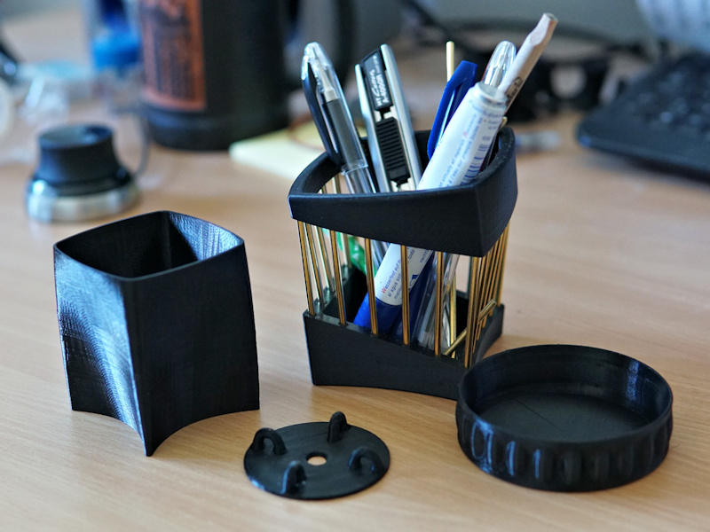
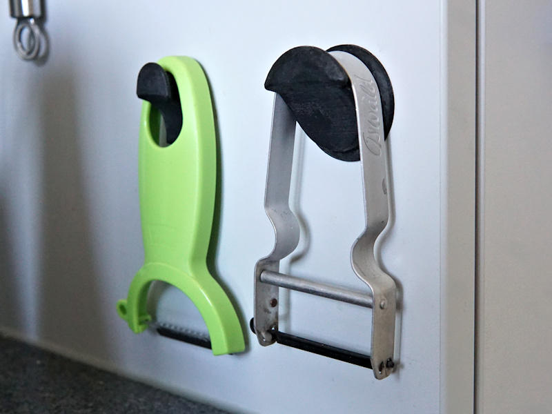
Now that we’ve got it all sorted out, let’s all heat up our printers and make some stuff. I hope you learned something in this tutorial. Finally, I’m going to show you a few of my own parts. They were all created in Viacad and printed on a Wanhao i3 Mini. Enjoy!
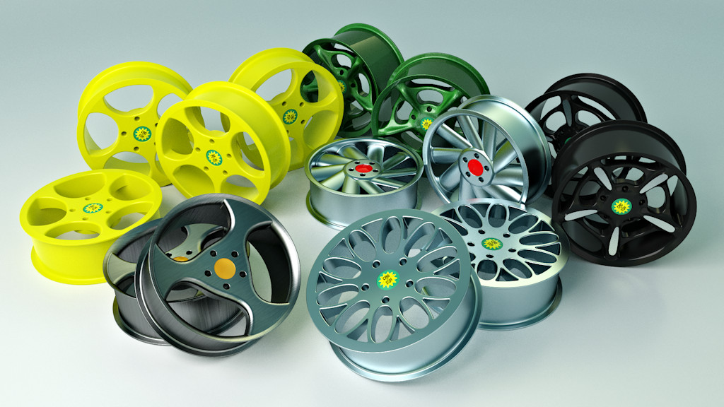
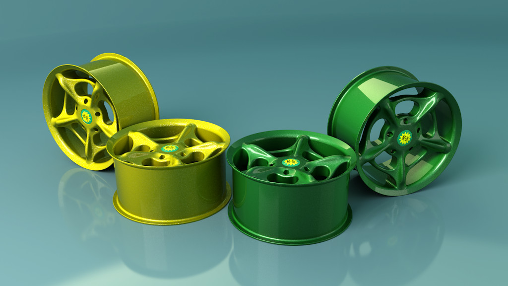
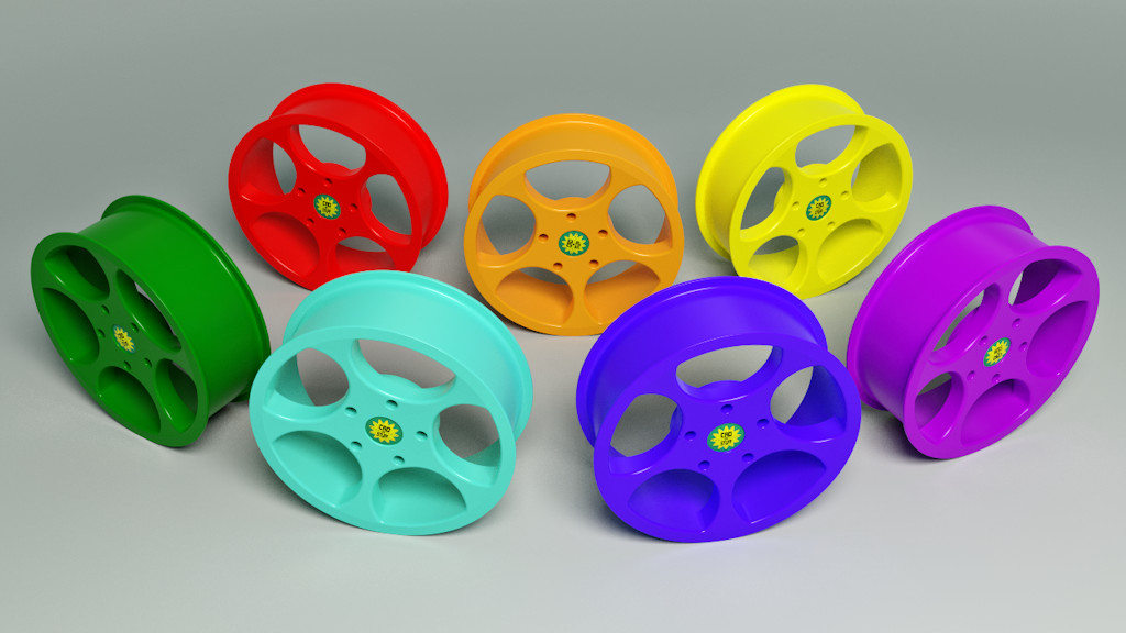
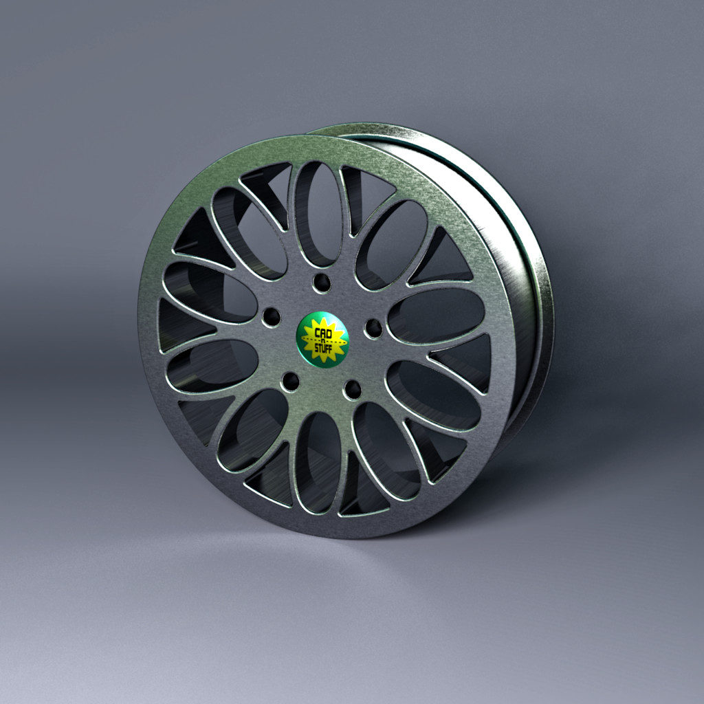
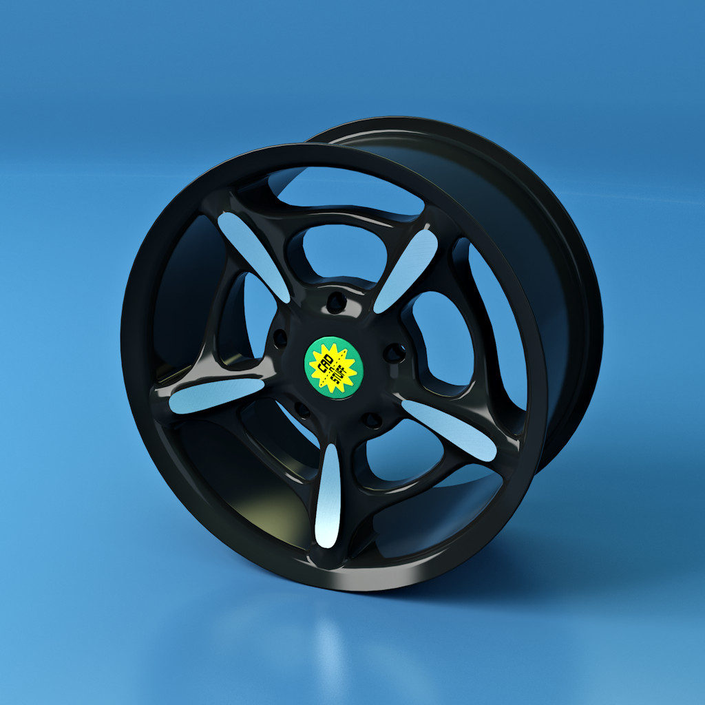
As a little side-project, just for fun, I designed a few car rims. As usual all the models were created in Viacad Pro, Rendered in Simlab and retouched in NeatImage and Paintshop Pro.
The 3 Boolean Tools are some of the most important tools in Viacad’s workbench. And even though their use is quiet straight forward, there are still some things to consider when using them. Unfortunately, Viacad isn’t a bug-free program (at all), which makes a clean workflow absolutely necessary. So, I wrote down a few thoughts about these tools.
Avoid Booleans (if possible)
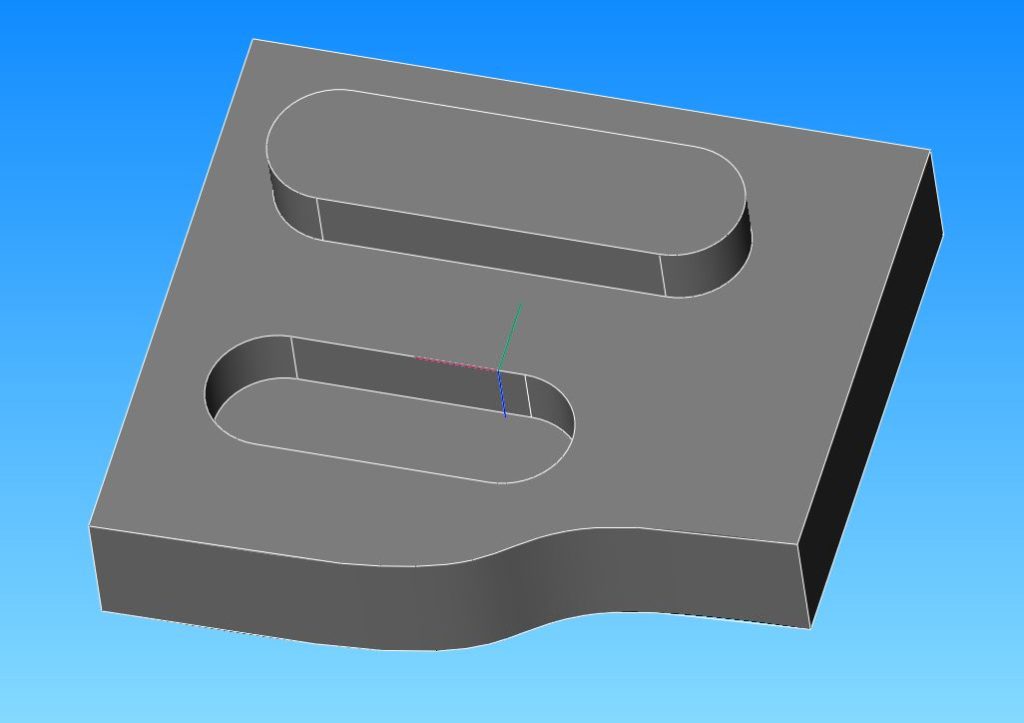
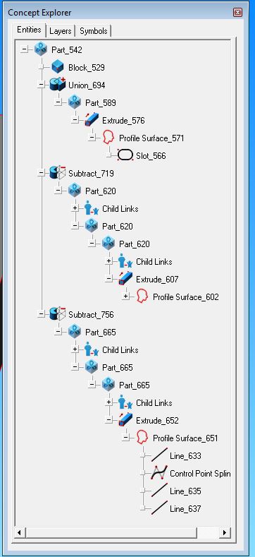
Yeah, I guess it’s a bit weird to make a tutorial about Booleans, just to write you shouldn’t use them. So why should Booleans even be avoided? Even though it seems a very simple operation, Boolean operations make things quiet complex. This makes it prone to break when modifying and rebuilding features in the middle of the feature tree. Down below you see how much the feature tree gets bloated, when using Booleans. The example is a (seemingly) very simple part.
In the first version I used only Booleans. I first extruded all the necessary geometry and in a second step combined/subtracted all the parts. And that’s how the feature tree looks like:
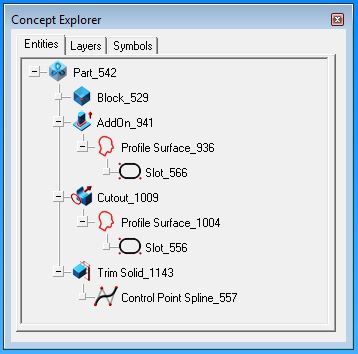
For the second try, I only extruded the main part. The rest of the geometry was made, using Protrusion Solid, CutOut Solid and Trim Solid. As you can see the feature tree is way less complex:
Apparently, things can get really fast really complicated. Nevertheless, Booleans are still an important and powerful tool in every CAD application. That’s why you should go ahead and read the following parts as well.
SAVE (a lot)
I guess that’s a recommendation for basically every program ever existing. A complex model, a weak computer and resource-hungry operations will certainly crash your model from time to time. That’s why you should save your files as often as possible. If you have a complex model, I even recommend to save more than 1 file. In that case I recommend you to save a new version after every major step. If your project is finished, keep the last version and delete all the previous files.
How to Bool
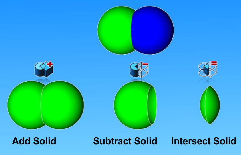
Using the Bool-commands is basically self-explanatory. Click on one of the 3 commands (Add Solid, Subtract Solid or Intersect Solid), pick the first solid and then the solid which you would like to combine. Add Solid and Subtract Solid allows you to combine multiple solids. Simply pick the first solid, and then select all the other solids while pressing Shift. Pressing CTRL when selecting the second object, will keep that object visible, even though you just combined it. This works only with Subtract Solid and Intersect Solid, though.
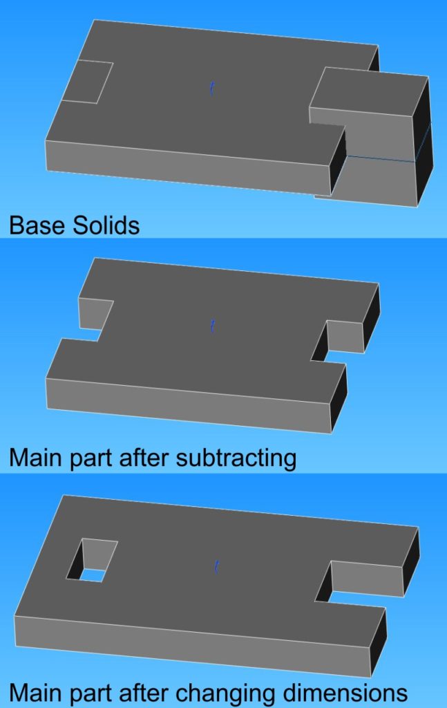
If you subtract a solid, make sure the subtracted solid overlaps the main solid. That way, the solid is easier to select. Another advantage is, that resizing of the main body doesn’t result in a faulty geometry.
Last but not least a little trick. After you have used a Bool-command, go to the Inspector. Under Object Properties/Data you have two nice little features. Number 1: you can choose to hide or show the parent geometry of the Boolean Operation. Right below that option, you will also find a feature to automatically add a fillet or chamfer to the geometry. If selected, all newly created edges are filleted in one go. That might save you quiet a bit of time, if you have a lot of geometry to fillet.
Like most people around the world, I’m currently sitting at home, waiting for this whole pandemic to pass. After countless hours of Netflix and YouTube, I stumbled across an absolutely beautiful video about black holes. If you have 7 and a half minutes to spare, you should definitely watch it. If you don’t, watch it anyway! So, there you go… (By the way, it’s a VR-/360°-video, so don’t hesitate to look around, during the video)
I’ll be honest. I’m in a love-hate relationship with Viacad Pro. On one side, it is a very capable little low budget CAD, that does everything I really need. But on the other side, I have also encountered the ugly side of this program. Slow development and bug fixing, just to name a few. So, I hope you’ll excuse if I flirt with the other CAD’s in town from time to time.
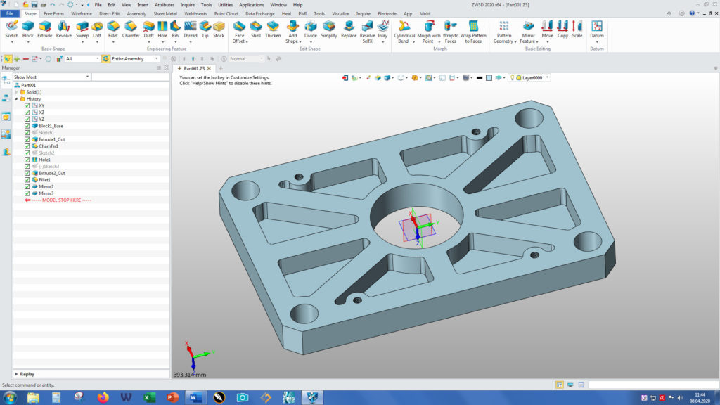
ViaCad’s ACIS-cousins Turbocad, Vellum and FormZ were not really to my taste and I’m still very sceptic about cloud-based stuff (the work morale of my router is not the highest, unfortunately). Another program I once downloaded for trial was ZW3D. It’s a CAD made in China and looks and feels a bit like Inventor or Solidworks. Unfortunately, the price is also in the range of these 2 programs. So, after the trial period I uninstalled it an didn’t think about it anymore.
However, a few days ago, I got an Email from ZWSOFT. It states, that due to Corona-virus, ZW3D is free for everyone until the end of May. So, if you need a CAD for the next 2 months, or just want to give this Chinese beauty a try, here’s the link: https://www.zwsoft.com/
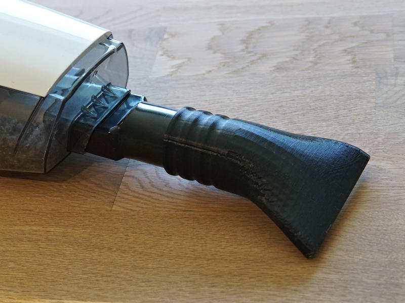
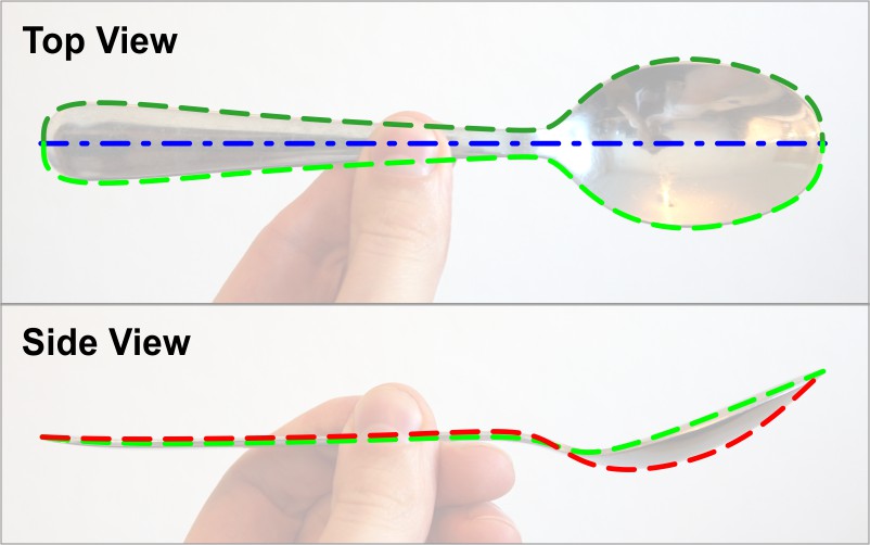
If there’s something common in every CAD-program, then it is the fact that there’s at least a dozen spoon tutorials available for each and every one of them. Weirdly, most of these tutorials are way to complicated for such a simple part. In the next few minutes, you will learn how to create a spoon in (probably) the simplest way possible.
Before you even think about starting up our computer, go to your kitchen drawer and get a spoon. If for some reason you don’t have a spoon lying around, don’t worry. There are a few pictures further down below 🙂
Now let’s
analyze that spoon in-depth. As you can see, the shape of a spoon can basically
be defined by 3 lines (2 of which are symmetrical!). And those 3 lines are all
we need to build this ominous soup-eating-device.
After we have done that, the most important part of this tutorial is already done.
After all, a few minutes of carefully analyzing a part can save you hours of
CAD-work. This is also the part, which many tutors and YouTube-creators seem to
completely ignore.
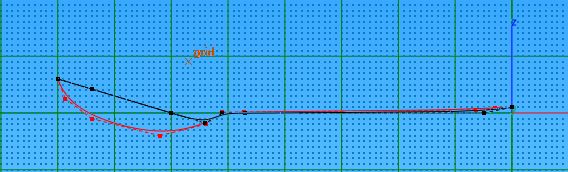
Finally, it’s time to start Viacad or SharkCad (or any other CAD-software, really). Go into Top View and make sure every Snap, except To Plane is activated. Draw the first curve using the Control Point Spline. Try to draw the curve with as few control points as possible. Around 10 should be enough. As we are mirroring this curve later, you have to align the first 2 control points vertically to the mirror axis. The same is also needed for the last 2 control points. That way, we achieve a tangency between the 2 mirrored curves.
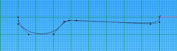
After that, go to the Front View. Switch to Select Deep and move the control points until the curve matches the green line in the front view of the photo above. It’s crucial to only move the points vertically, as moving the points sideways also changes the Top-View contour.
At this point, go to Front- and Isometric View to make sure the whole curve looks as it should. While still in Top View, right click the line and click on Show Points. Count your points and try to remember the number until the next step 🙂
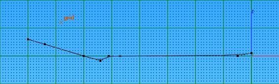
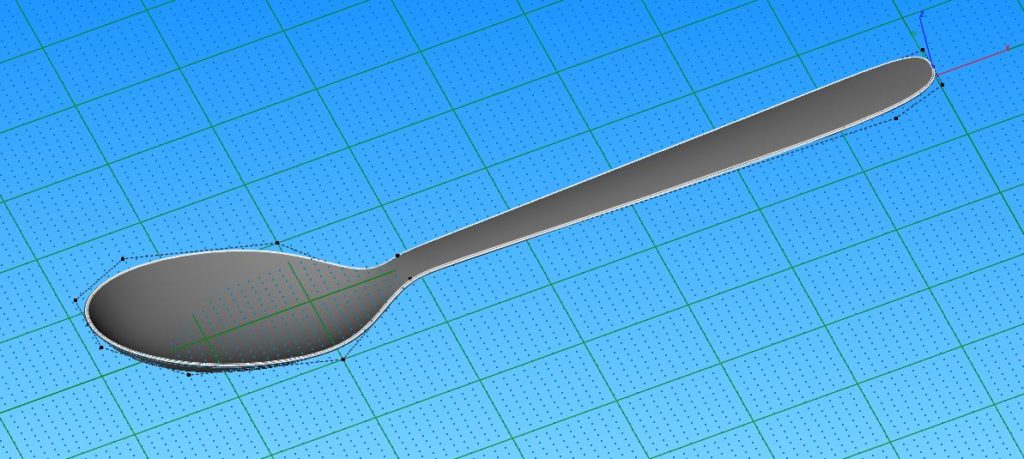
Still remember the number of control points of the first line? Wonderful. Switch to Front View and draw the second line with just as many points. Try to position the points close to their counterparts of the first line. Just don’t forget that at the start and end of the line, there are 2 points on top of each other. This even distribution of control points is necessary to create an absolutely clean and smooth surface. This might be a bit overkill for such a simple object, but it is absolutely necessary if you have to create more complex geometry some time.
For the 3rd
line, switch to Top View and mirror the first curve using Linked
Mirror.
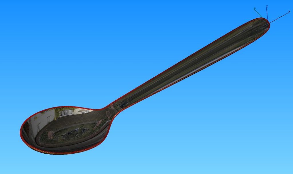
Now we are finally ready to create a surface and a solid. Click on Skin Surface and select all 3 curves. After that, click on Thicken Solid to add some meat to that surface. Last, but not least smooth the edges of the solid using Blend Edge. If you followed the Tutorial closely, your spoon should more or less look like this:
And that is already the end of this tutorial. Enjoy your new CAD-spoon and get yourself some digital soup.
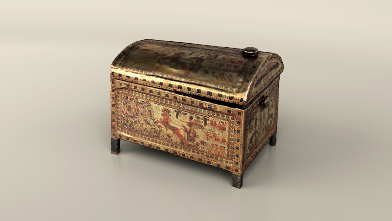
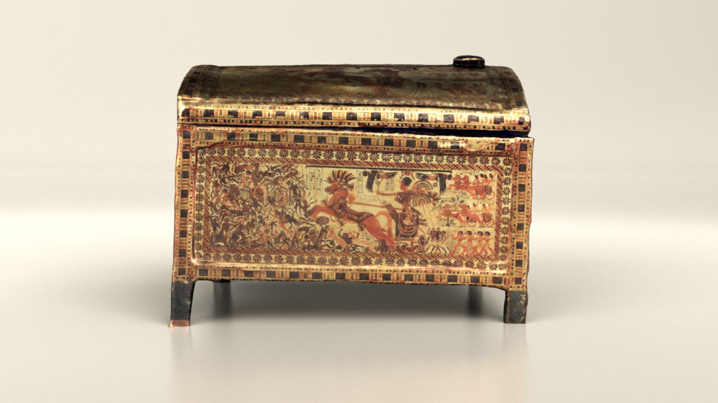
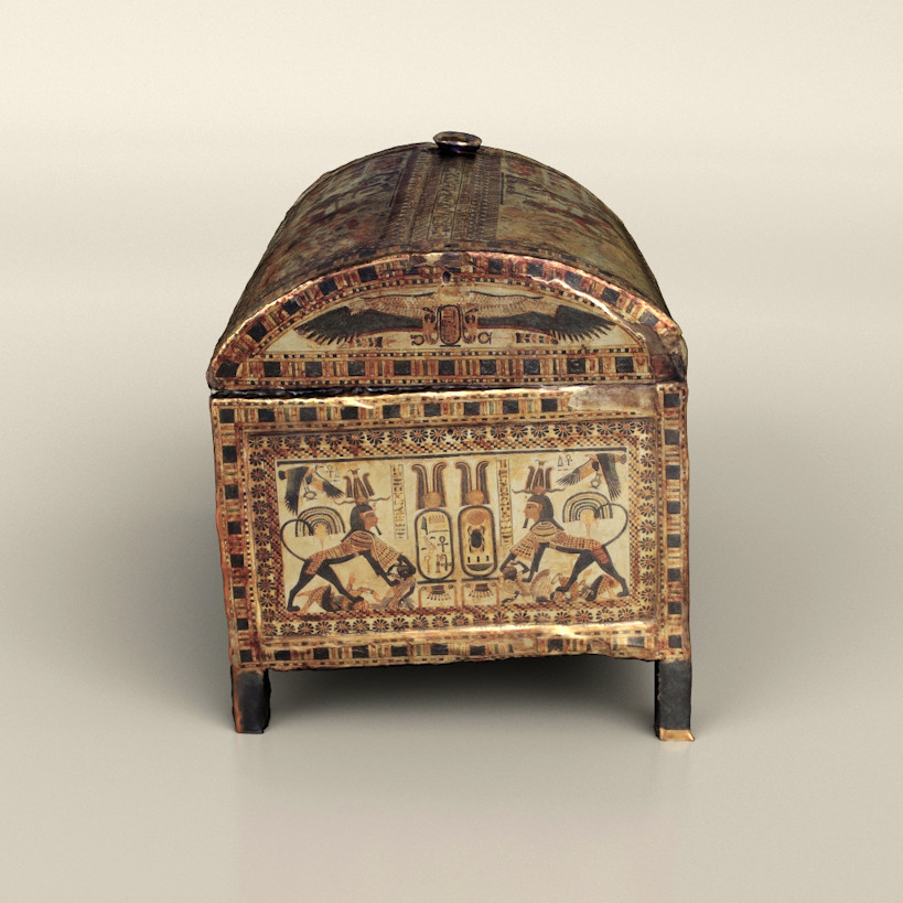
A few days ago I found a very cool 3d-model on sketchfab. It’s the model of a chest that was found in the tomb of the Pharao Tutankhamun. As a big fan of ancient cultures I had to download and render that model. The original file (And a lot of other similar stuff) can be found here
Everything was rendered in Simlab Composer 8 and slightly retouched in Corel Paintshop Pro 2019
In the last Viacad tutorial Viacad User Interface Customization, we improved our workflow by customizing its user interface. In this second parts, I’ll share a bit of my view and knowledge about keyboard shortcuts.
There are
people in this world who have a keyboard shortcut for everything. Copying, pasting,
lofting, mirroring, extruding, roasting chicken and many more (The last-mentioned
shortcut is not supported in any Punchcad version, unfortunately). And even
though I am far from being one of those guys, I still have a few frequently used
shortcuts.
If you have followed my last Viacad tutorial closely, you may have altered your user interface to get every important feature with 1 single click. So, why do we even need keyboard shortcuts? Mostly, because it’s convenient if you can access a feature in multiple ways. Why drag the mouse cursor from 1 edge of your 30″ flatscreen to the other, when you can simply press 1 button? Way more important however, is the fact that you are able to create a shortcut for features that can’t be accessed via an icon. Some commands can only be accessed in the menu bar, which leads to a lot of clicking.
So how do
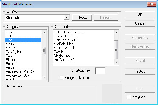
you even create keyboard shortcuts in Viacad? It’s quite simple.
Go to File -> Shortcuts in the menu bar. In the newly opened window, you can see all the available commands. Apart from changing these settings, you can also print out a list with all the corresponding shortcuts. The list is absurdly long though. So, you are better off writing down the needed commands by yourself.
So, what
features deserve a shortcut? The answer to this question heavily depends on how
many shortcuts you want to use and what kind of work you do.
Yet, there are still a few commands, which are a must.
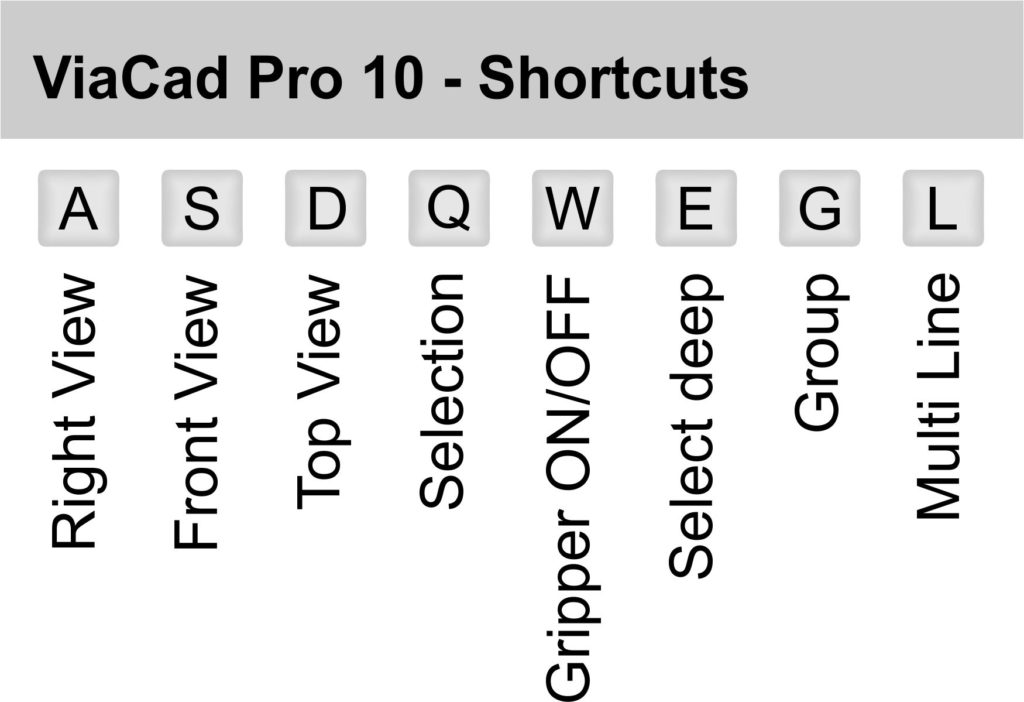
Views – Although right- front- and top-view can already be accessed using ALT + 1, 2 or 3 I recommend to change that, to get rid of the unnecessary ALT key.
Selection – Switching between normal selection and select deep occurs usually very often. So there’s no reason not to give these commands an appropriate shortcut.
Gripper – Shure, a simple “right-click -> Gripper OFF” is very quick already, but using a single key is still quicker!
Multiline – There’s basically not a single .vc3 file on my computer, that doesn’t have them. I guess that deserves a unique key-binding, doesn’t it.
Finally, here’s my list of my “absolutely needed” keyboard shortcuts:
And that’s already
the end of my second Viacad tutorial. Stay tuned for more!!!