Yet Another Spoon Tutorial

If there’s something common in every CAD-program, then it is the fact that there’s at least a dozen spoon tutorials available for each and every one of them. Weirdly, most of these tutorials are way to complicated for such a simple part. In the next few minutes, you will learn how to create a spoon in (probably) the simplest way possible.

Before you even think about starting up our computer, go to your kitchen drawer and get a spoon. If for some reason you don’t have a spoon lying around, don’t worry. There are a few pictures further down below 🙂

Now let’s 
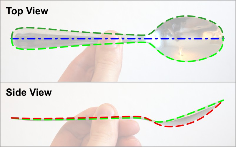
analyze that spoon in-depth. As you can see, the shape of a spoon can basically be defined by 3 lines (2 of which are symmetrical!). And those 3 lines are all we need to build this ominous soup-eating-device.
After we have done that, the most important part of this tutorial is already done. After all, a few minutes of carefully analyzing a part can save you hours of CAD-work. This is also the part, which many tutors and YouTube-creators seem to completely ignore.

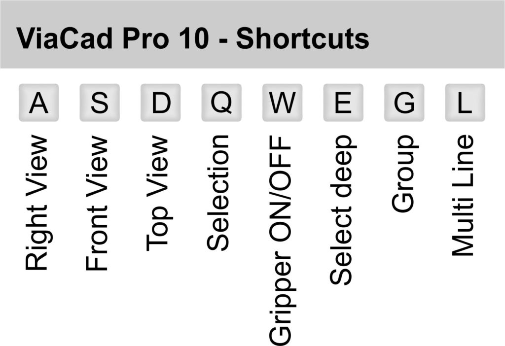
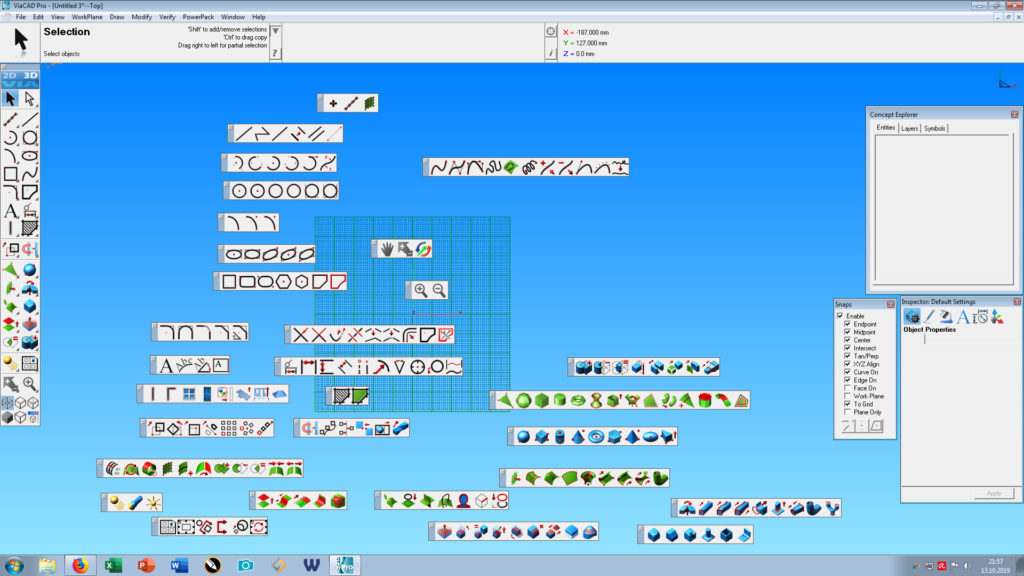
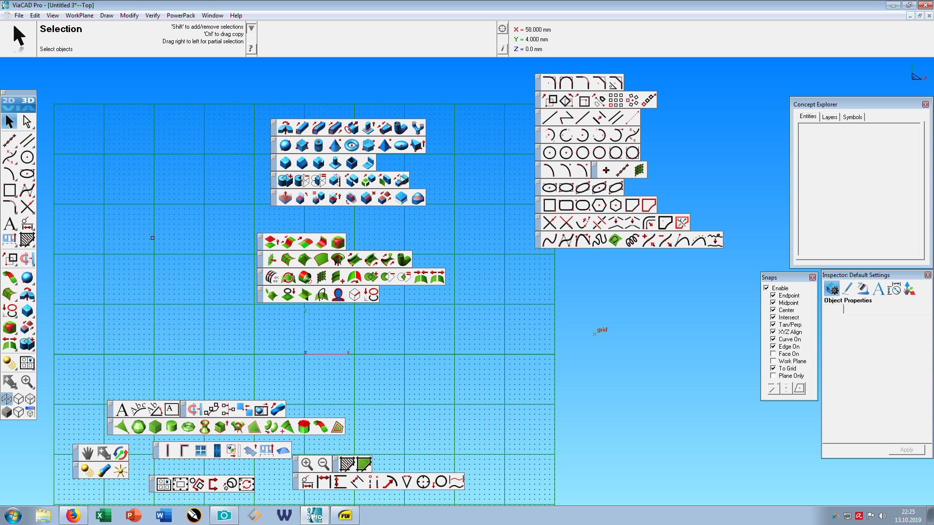
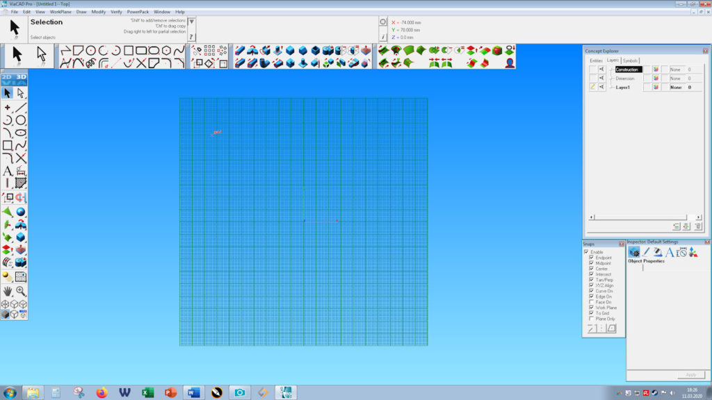
Finally, it’s time to start Viacad or SharkCad (or any other CAD-software, really). Go into Top View and make sure every Snap, except To Plane is activated.
Draw the first curve using the Control Point Spline. Try to draw the curve with as few control points as possible. Around 10 should be enough. As we are mirroring this curve later, you have to align the first 2 control points vertically to the mirror axis. The same is also needed for the last 2 control points. That way, we achieve a tangency between the 2 mirrored curves.


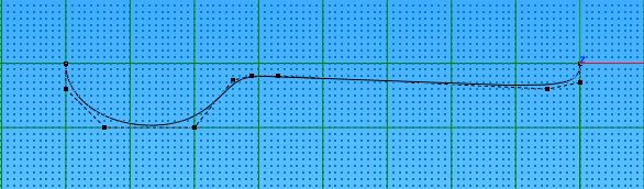
After that, go to the Front View. Switch to Select Deep and move the control points until the curve matches the green line in the front view of the photo above. It’s crucial to only move the points vertically, as moving the points sideways also changes the Top-View contour.


At this point, go to Front- and Isometric View to make sure the whole curve looks as it should. While still in Top View, right click the line and click on Show Points. Count your points and try to remember the number until the next step 🙂

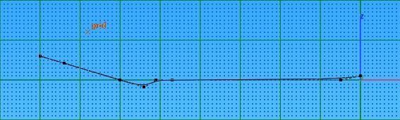
Still remember the number of control points of the first line? Wonderful. Switch to Front View and draw the second line with just as many points. Try to position the points close to their counterparts of the first line. Just don’t forget that at the start and end of the line, there are 2 points on top of each other. This even distribution of control points is necessary to create an absolutely clean and smooth surface. This might be a bit overkill for such a simple object, but it is absolutely necessary if you have to create more complex geometry some time.

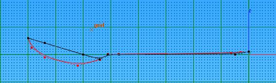
For the 3rd line, switch to Top View and mirror the first curve using Linked Mirror.

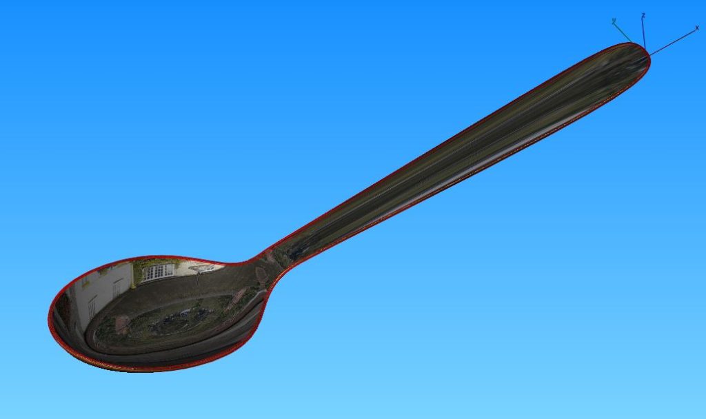
Now we are finally ready to create a surface and a solid. Click on Skin Surface and select all 3 curves. After that, click on Thicken Solid to add some meat to that surface. Last, but not least smooth the edges of the solid using Blend Edge. If you followed the Tutorial closely, your spoon should more or less look like this:

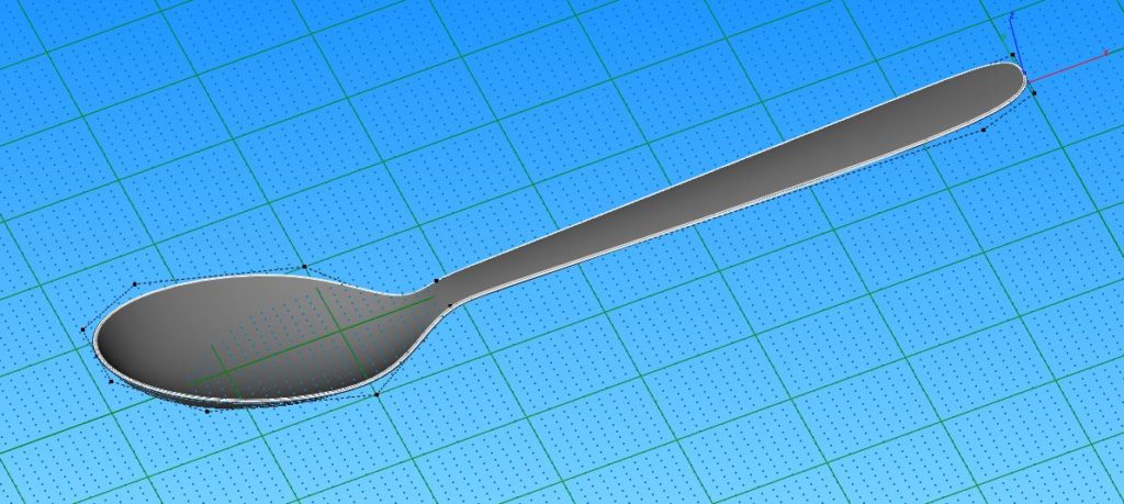
And that is already the end of this tutorial. Enjoy your new CAD-spoon and get yourself some digital soup.

Rendering a 3000 year old chest

A few days ago I found a very cool 3d-model on sketchfab. It’s the model of a chest that was found in the tomb of the Pharao Tutankhamun.
As a big fan of ancient cultures I had to download and render that model. The original file (And a lot of other similar stuff) can be found here

Everything was rendered in Simlab Composer 8 and slightly retouched in Corel Paintshop Pro 2019

ViaCAD Shortcuts

In the last Viacad tutorial Viacad User Interface Customization, we improved our workflow by customizing its user interface. In this second parts, I’ll share a bit of my view and knowledge about keyboard shortcuts.

There are people in this world who have a keyboard shortcut for everything. Copying, pasting, lofting, mirroring, extruding, roasting chicken and many more (The last-mentioned shortcut is not supported in any Punchcad version, unfortunately). And even though I am far from being one of those guys, I still have a few frequently used shortcuts.

If you have followed my last Viacad tutorial closely, you may have altered your user interface to get every important feature with 1 single click. So, why do we even need keyboard shortcuts? Mostly, because it’s convenient if you can access a feature in multiple ways. Why drag the mouse cursor from 1 edge of your 30″ flatscreen to the other, when you can simply press 1 button?
Way more important however, is the fact that you are able to create a shortcut for features that can’t be accessed via an icon. Some commands can only be accessed in the menu bar, which leads to a lot of clicking.

So how do you even create keyboard shortcuts in Viacad? It’s quite simple.

Go to File -> Shortcuts in the menu bar. In the newly opened window, you can see all the available commands. Apart from changing these settings, you can also print out a list with all the corresponding shortcuts. The list is absurdly long though. So, you are better off writing down the needed commands by yourself.

So, what features deserve a shortcut? The answer to this question heavily depends on how many shortcuts you want to use and what kind of work you do.
Yet, there are still a few commands, which are a must.

  • Views – Although right- front- and top-view can already be accessed using ALT + 1, 2 or 3 I recommend to change that, to get rid of the unnecessary ALT key.
  • Selection – Switching between normal selection and select deep occurs usually very often. So there’s no reason not to give these commands an appropriate shortcut.
  • Gripper – Shure, a simple “right-click -> Gripper OFF” is very quick already, but using a single key is still quicker!
  • Multiline – There’s basically not a single .vc3 file on my computer, that doesn’t have them. I guess that deserves a unique key-binding, doesn’t it.

Finally, here’s my list of my “absolutely needed” keyboard shortcuts:

And that’s already the end of my second Viacad tutorial. Stay tuned for more!!!

Viacad User Interface Costumization

Many people around the world use the same 2-3 programs all day long. And yet, many of them could be much more productive, if they spent a little time to learn and customize their applications.
In this tutorial I will show you, how you can speed up your modeling workflow by customizing the Viacad user interface (UI) to your liking.

So, what is important for a good UI? One vital factor is space. Especially people with small screens want to keep as much of the available space as modeling area. On the other hand, having many toolboxes and features on the screen leads to fewer (unnecessary) clicks, which improves your speed of working.
So, if you are tired of tear-away toolboxes and clicking around like a maniac, keep on reading…

To start, open Viacad or Sharkcad. Then, tear of or open every toolbar available and move it into your workspace (Yes, EVERY toolbar). Depending on which version of Viacad/Sharkcad you use, it should look more or less like this:

Once that’s done, group all those toolbars on-screen. Put all the solid features to one place, mesh features to another and so on.

Now before we continue this tutorial, you might want to have an in-depth look at all those features. It’s quite possible you find a few features you didn’t even know existed. Maybe there’s even 1 or 2 feature you could use in your daily work.

Now that your computer screen is littered with features, take a screenshot. Print it out and get yourself a hot cup of coffee. You deserve it! Take the printed screenshot and cross out every feature you don’t need. At the end, only your most-used features should remain. Remember, every feature is still available from the main toolbar or the menu bar, so don’t worry about removing too many features.

Back in Viacad it is time to create the new toolbars. Go to Window -> Custom Tools -> New palette, to create a new toolbar.

You are completely free how many rows and columns of icons you want and how big these icons should be. The absolute maximum is 50 features per toolbar, but you probably won’t need that many. I recommend to make a about 3-5 toolbars that cover all the different fields (All solid tools in one menu, all surface tools in another, etc.). Count how many features you need in each toolbar and adjust them however you like them. As soon as you have created these empty toolbars, you can fill them with the desired features by rightclick-dragging them from a standard toolbar to your own custom toolbar.

All you have to do now is putting these custom toolbars at the desired place of your screen and enjoy your new workspace. In the picture below you see my personal workspace.
Every important feature ist just one simple click and yet the workspace still looks very neat and tidy.

Alright, we’re done. Time to get another cup of coffee

The Ultimate Surfacing Tutorial

Alright, that title might be a bit misleading, but isn’t everyone exaggerating on the internet? Anyway, Surface modeling on any CAD can be quite tricky. Especially the so-called “Class-A”-modeling seems to be witchcraft to the average CAD user. Luckily there are tutorials online for everyone and everything.
As I am a bloody amateur myself, I might be the wrong guy for such a topic. But why should I make something that already exists anyway?
I found an absolutely amazing introduction to surface modeling on the internet. It’s made by the guys from Autodesk Alias. Alias is the ultimate surfacing software right now. So, I assume the Alias-people are more than capable to make such an “Ultimate Surfacing Tutorial”.
There might be a few parts which are for Alias only, but 90% of their tutorials and tips work with basically any CAD.

Anyway, here’s the link:
https://knowledge.autodesk.com/support/alias-products/getting-started/caas/CloudHelp/cloudhelp/2019/ENU/Alias-Tutorials/files/GUID-358AC713-21D6-40B5-9C43-74D26334B3F0-htm.html